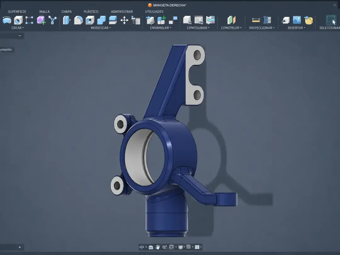
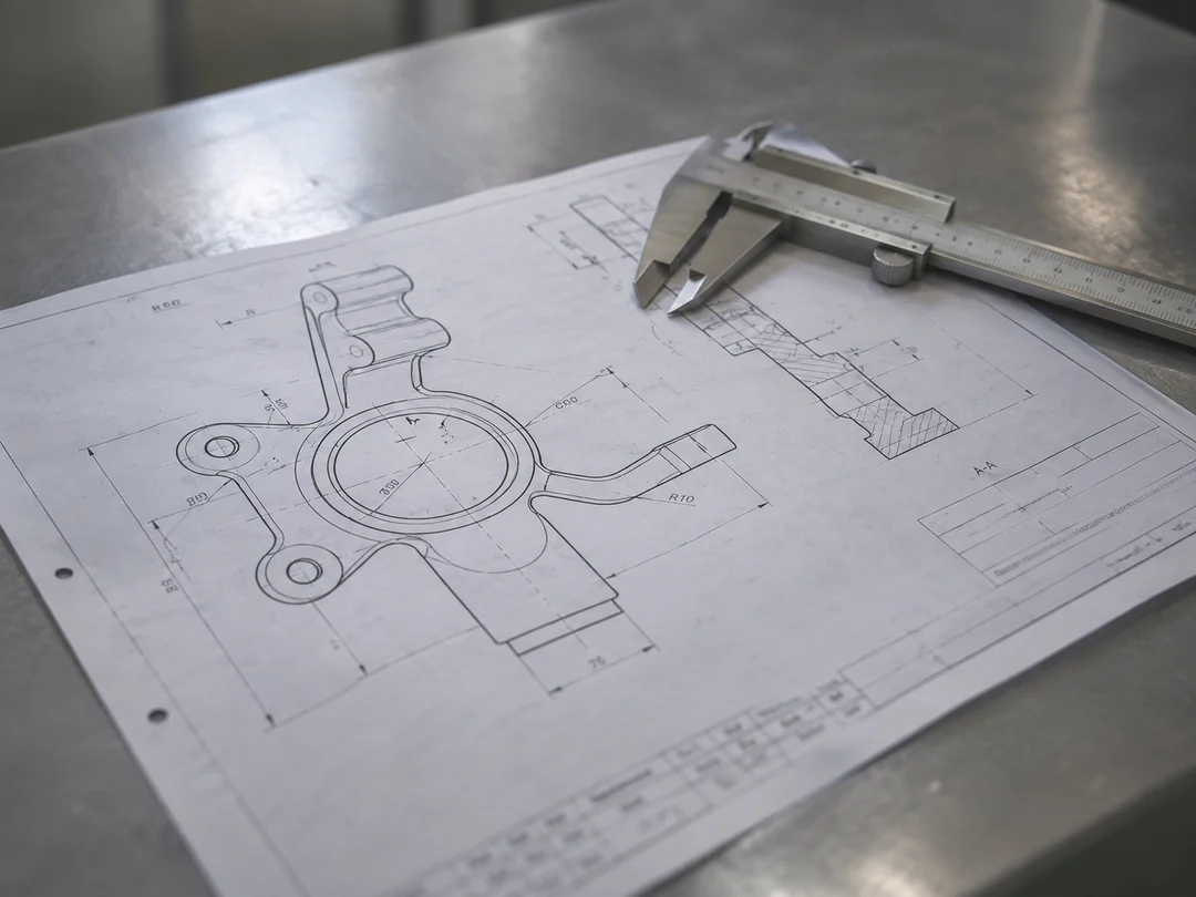
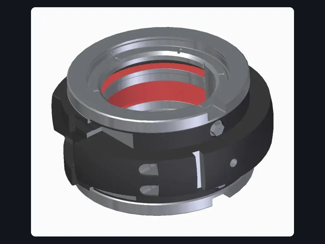
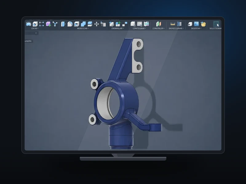
Parametric modelling from a functional requirement, a sketch or an existing part.
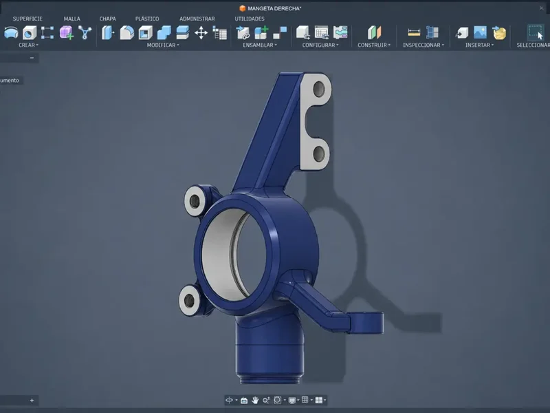
3D design, DFM/DFA, FEA simulation and production drawings to take your part from concept to the shop floor, for companies in Spain and Europe.
We turn a functional requirement into a manufacturable drawing, validated for tolerances, material and process, and apply DFM/DFA from the first sketch. What comes out of here is made through our CNC machining or sheet metal and structures, and verified by dimensional inspection.
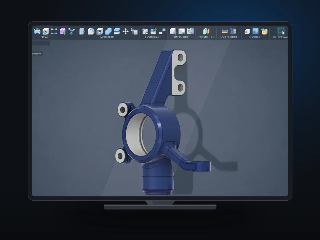
Parametric modelling from a functional requirement, a sketch or an existing part.
We optimise the design for manufacture and assembly from the first sketch. If you already have one, we audit it and propose improvements.
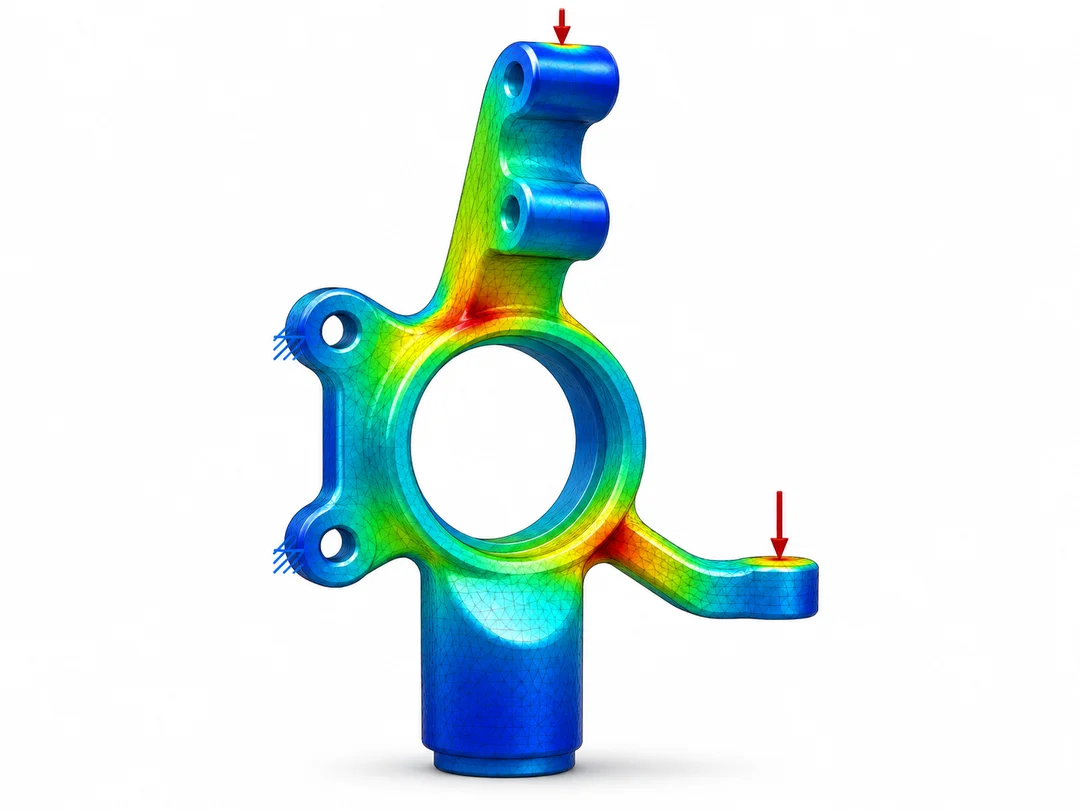
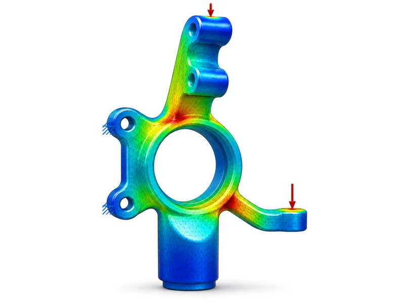
Structural, fatigue, thermal and modal analysis.
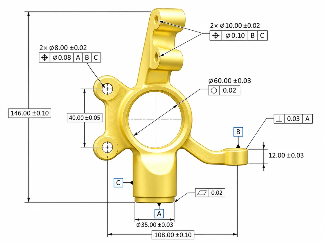
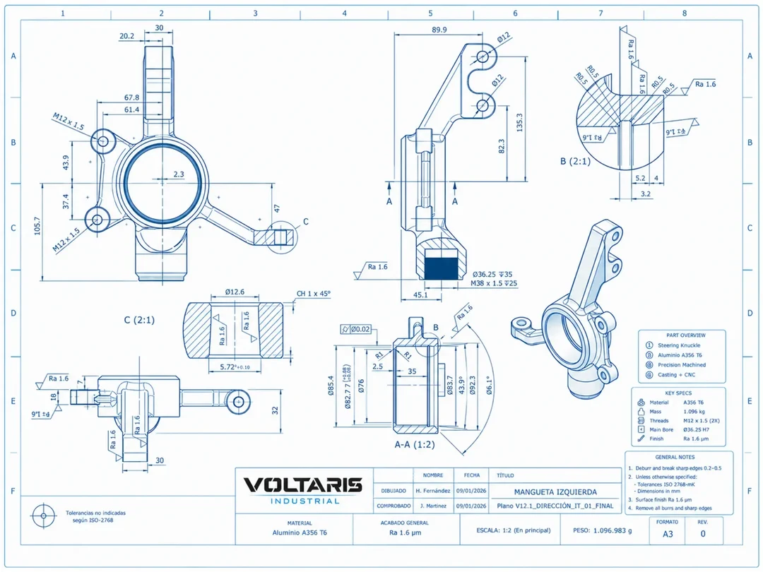
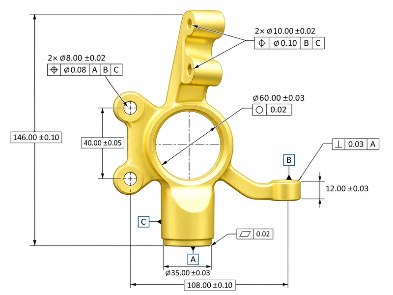
Application and interpretation of geometric tolerances to ASME Y14.5 and ISO 1101.
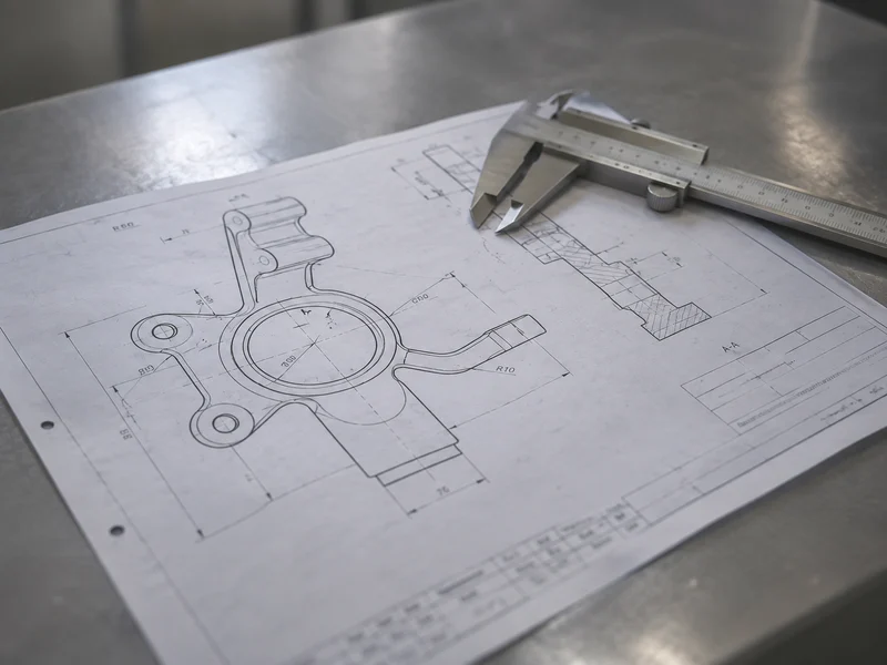
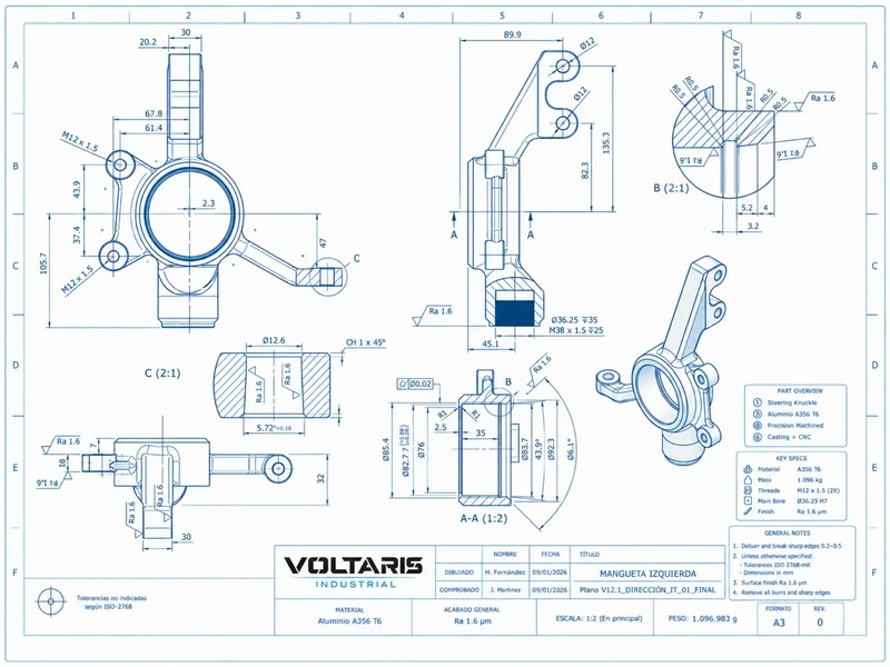
Standardised 2D drawings with views, sections, dimensions, tolerance table, bill of materials (BOM) and notes.
Assembly manuals, process sheets and inspection instructions.
When there is no drawing, we rebuild the model from the part itself, in four steps.
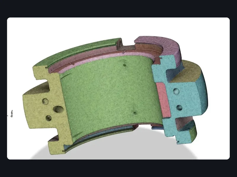
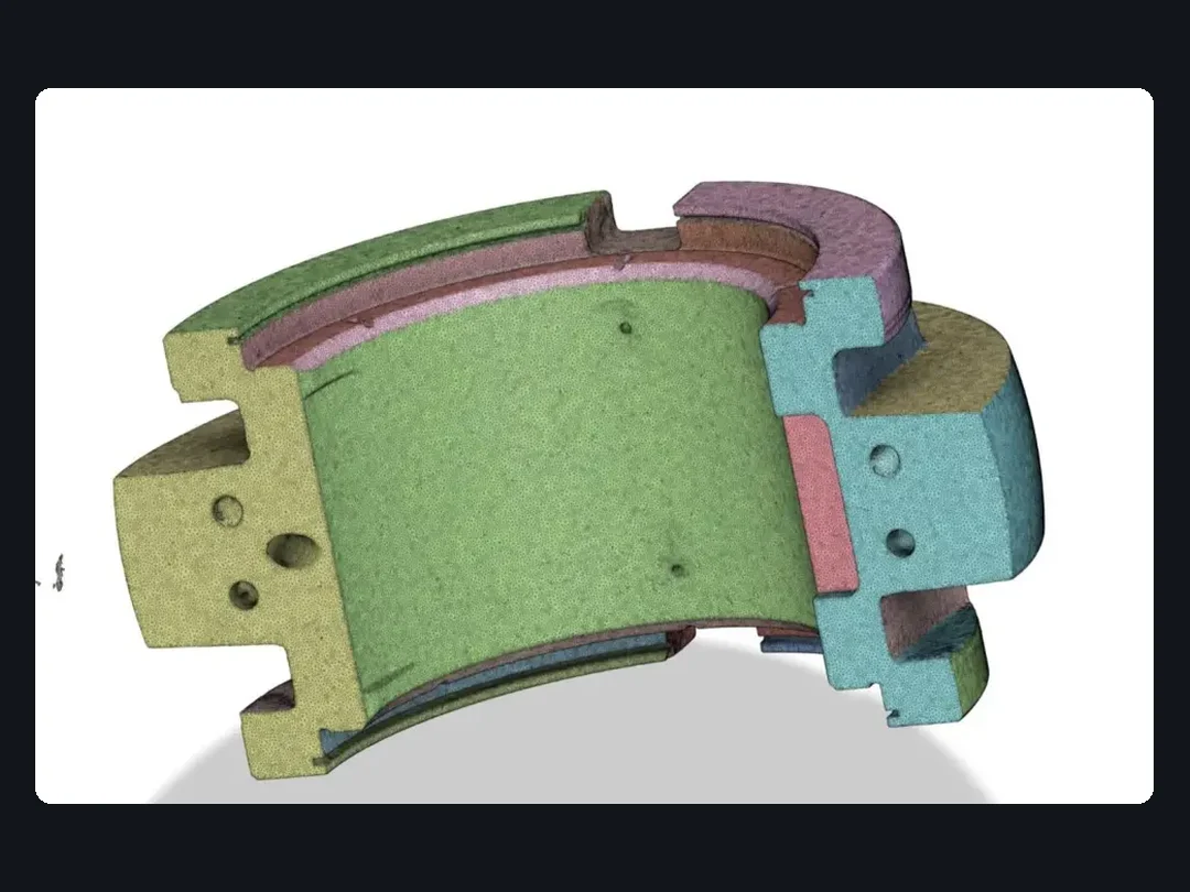
We digitise the part with a 3D scanner so we start from its real geometry, not from a drawing that does not exist.
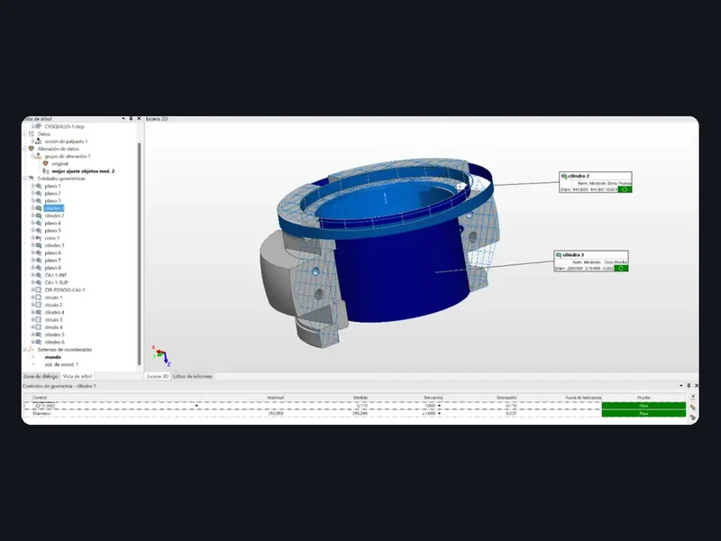
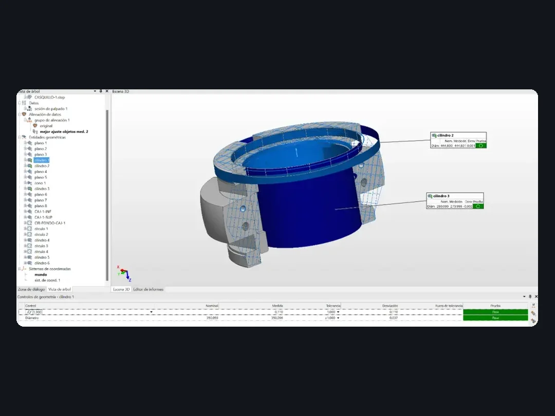
We probe the critical and constraining dimensions: the ones the model must respect without exception.
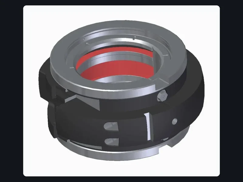
We rebuild the CAD model from the mesh and the measured dimensions, ready to manufacture or modify.
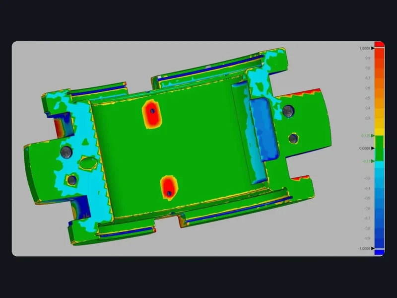
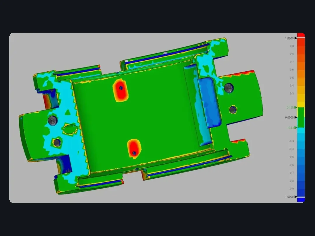
We compare the CAD against the scan in a colour deviation map to confirm the model reproduces the part.
Native 3D CAD model plus neutral STEP/IGES files, standardised 2D drawing with dimensions, GD&T and notes, bill of materials (BOM), FEA report with loads and results, and a signed design review document.
We dimension to ISO 1101 and ASME Y14.5, with ISO 286 fits and ISO 2768 general tolerances. We design in carbon steel, stainless steels, aluminium, titanium, technical alloys and engineering plastics, using SolidWorks, Fusion 360, Inventor, NX and Solid Edge, and we measure with FaroArm and PolyWorks Inspector. We work for a range of industrial sectors. To request a quote, send your drawing or requirements through our quote request form.
Frequently asked questions
Yes. We carry out reverse engineering: we 3D-scan the part, measure its critical dimensions, rebuild the CAD model and validate it with a deviation map against the scan.
Native 3D CAD model plus STEP/IGES, standardised 2D drawing with dimensions, GD&T and notes, bill of materials (BOM), FEA report with loads and results, and a signed design review document.
Yes. We audit the existing design for manufacturing and assembly (DFM/DFA) and propose improvements before the part is released to production.
We respond within 24 working hours of receiving your drawing or requirements, with a technical analysis of what you need.